.png)
.png)
.png)
All the TinkerCAD Circuits are made by
Divyansh Bansal and Shalabh Kamboj
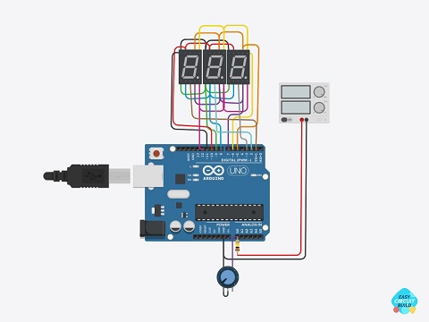
7 Segment Voltmeter using Arduino
In this circuit, we are multiplexing 3:7 segment display and by the use of a potential divider, the analog signal is generated which is decoded by Arduino and is displayed on 7 segment display. The voltage input for this voltmeter is 0-50 volt DC.
Tinker this
NE555 Flasher
This is the most popular flasher circuit using NE555 timer IC. In this circuit we hardly require some basic components such as a Capacitor for delay time, resistor to adjust the delay and for output representation, an LED is attached to the output.
Tinker this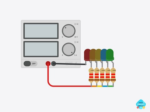
Battery Level Indicator
This is a simple and easy circuit to view charging of your battery, in this power supply is placed to demonstrate variable voltage similar to that of charging of a battery. The circuit requires a few LEDs and resistors to do its job.
Tinker this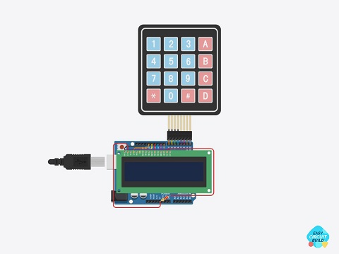
Calculator using Arduino
This is a good DIY project circuit. In this circuit we are pairing LCD display and keypad with Arduino to make a proper working calculator, just provide input through the keypad, and after calculation, the result is displayed on the LCD display.
Tinker this
Dark Active Detector
This circuit has multiple applications such as automatic street light, staircase light, dark activation, etc. In this circuit, we can adjust the time duration for a load. As the LDR sense, the variation in the light intensity circuit gets activated.
Tinker this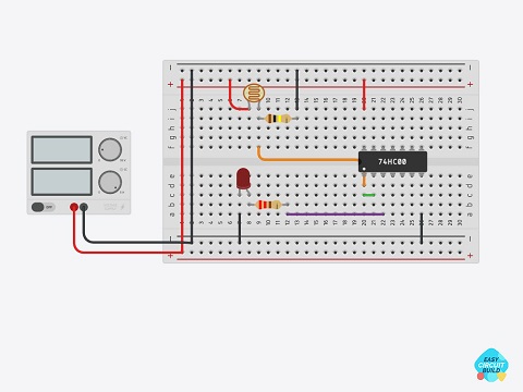
Dark Detector using GATES
The circuit is very basic. In this circuit, we use a photoresistor in which resistance varies according to the light intensity and a NAND gate with shorted inputs which means if the light intensity is more the output will be False and vice-versa.
Tinker this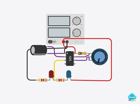
Double Flasher using NE555
This is a normal double flasher circuit used in emergency vehicles, flip-flops, basic traffic lights and for decorative purposes, the circuit is made around NE555 timer IC. In this, we can adjust delay using a capacitor and the ratio of resistors.
Tinker this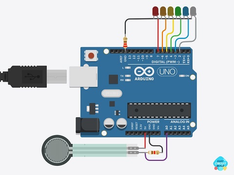
Force Sensor
In this circuit as per the name, we are using a force sensor. LEDs are placed on their respective pins to represent the amount of force applied to the force sensor. Here we are using Arduino for manipulating and converting analog signal to binary.
Tinker this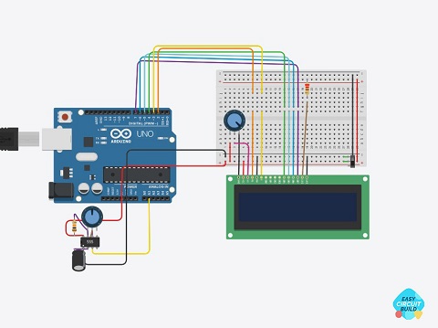
Frequency Counter
In this circuit, for demonstration, we are using a 555 timer IC circuit as a frequency generator sending input signals to Arduino. Arduino is displaying the value of frequency on 16 X 2 LCD display at 4 bits. We can also use I2C communication.
Tinker this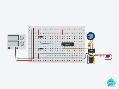
Game Trigger
This is a simple demonstration circuit that shows the working of how a game gets triggered. It uses the concept of NOR gate that means if the two players are not engaged in the match then the gate between them gets started or gets triggered.
Tinker this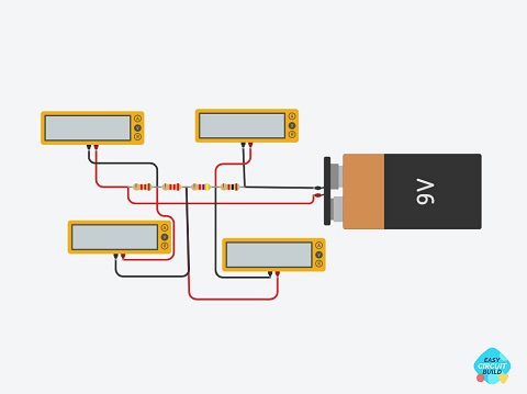
KVL Circuit
KVL, states that “in any closed-loop, the total voltage around the loop is equal to the sum of all the voltage drops within the same loop” which is also equal to zero. In other words, the algebraic sum of all voltages within the loop must be equal to zero.
Tinker this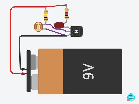
LDR Circuit
This is one of the easiest, most common, and cheapest circuit with minimal requirements that is LDR, transistor, and a LED. We can make both Daylight and Nightlight detection systems using this basic circuit.
Tinker this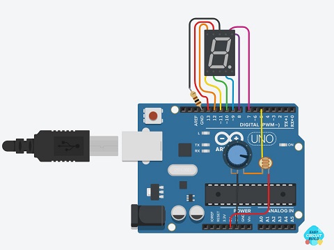
LDR Counter using Arduino
In this circuit we send an analog signal by making a potential divider that is displayed on 7 segment display using multiplexing, Whenever there is a change in light intensity the count number gets increased, after every 9 no. count the counter gets reset.
Tinker this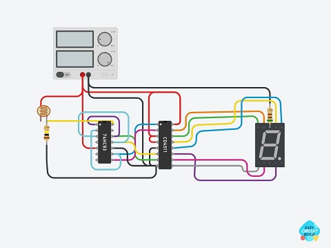
LDR Counter using Gates
Here we use a 7 segment display to display output, a CD4511 IC which is a BCD to 7 segment converter, a 7493 IC which is a BCD converter, which takes input from the LDR converts it to BCD and then BCD is converted to 7 segment and is displayed.
Tinker this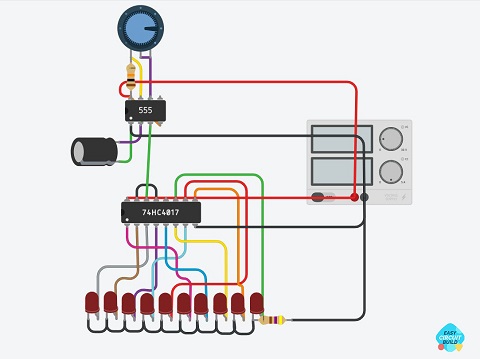
LED Chaser using NE555
Here we are using a NE555 Timer IC circuit with variable flashing speed to provide a clock to the shifter IC (CD4017) for output we have attached an LED on each output pin of the shifter IC, to represent the working of the LED chaser circuit.
Tinker this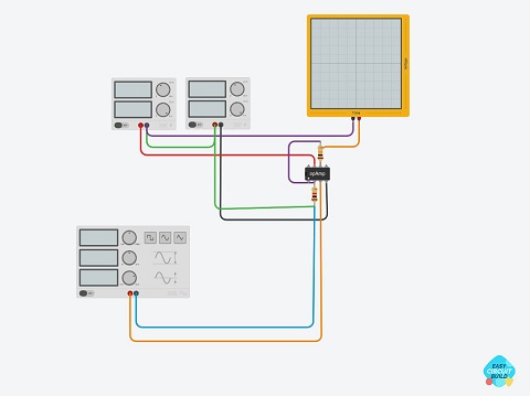
Operational Amplifier
An Operational Amplifier is a voltage amplifying device designed to be used with external feedback components such as resistors and capacitors between output and input terminals. It has two types of inputs named inverting and non-inverting.
Tinker this
Square Wave Generation
The square wave generator is commonly used in low-cost UPS/Inverters circuits. We use NE555 timer IC as a base IC which features flipflop functions, that generates square wave impulses. The frequency can be tuned by the rating of components.
Tinker this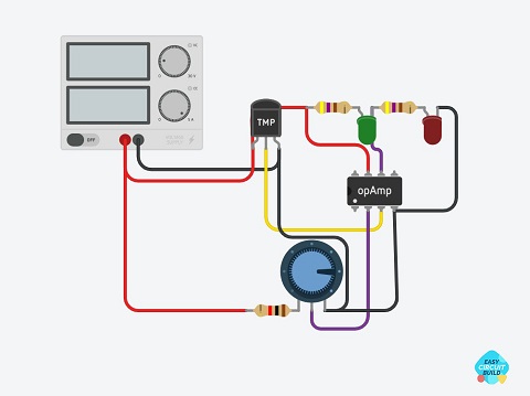
Temperature Sensor using LM35
This is a temperature sensor circuit using LM35 (temperature sensor) and LM741 (Opamp). The temperature sensor triggers the opamp as per the temperature sensed from the environment and activated the LED.
Tinker this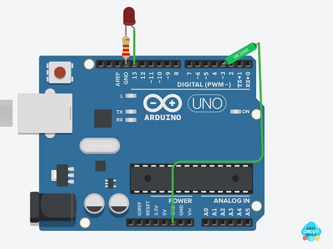
Tilt Sensor using Arduino
In this circuit, we are using a BC547 NPN transistor. The Tilt sensor work as a variable resistance whose resistance varies with Tilt providied to the sensor, the variation of resistance of the tilt sensor triggers the transistor to activate the output load.
Tinker this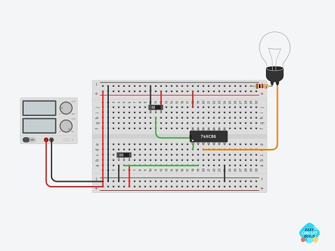
Two Way Switch
This is a simple circuit that has many applications, from staircase lighting to two-way room lights. It contains an XOR gate which means if the two inputs to the gate are different only then it gives the output, else its output is off.
Tinker this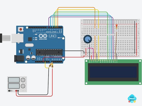
Voltmeter
In this circuit, we are multiplexing 3:7 segment display and by the use of a potential divider, the analog signal is generated which is decoded by Arduino and is displayed on 7 segment display. The voltage input for this voltmeter is 0-50 volt DC.
Tinker this